Some of the RC-522 RFID card reader modules that can be bought on ebay / aliexpress have a problem: they do not read all (types of) cards they should be able to read. In this blog post I want to explain how to recognize these faulty readers and how to fix them. (There is a more detailed post in Dutch)
Choosy Cardreaders
Lets start at the beginning:
At MakerSpace Leiden those RFID-RC522 card readers are used in the access-system and AC-node system. Participants of the MakerSpace can scan their cards to get access to the MakerSpace (access system) or to enable power to heavy machinery that requires training (After completing the training ; AC-node system).
Most use their OV-chipkaart. (Public transport card, Oyster card for UK readers).
The problem that surfaced is that some of the RC522 card readers won’t read some cards (Including the OV-chipkaart).
That’s obviously a problem when the door won’t open or the machine won’t start, or your project using those card readers doesn’t work with all the cards it should be working with.
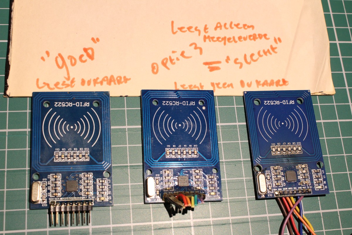
Good v.s. Bad
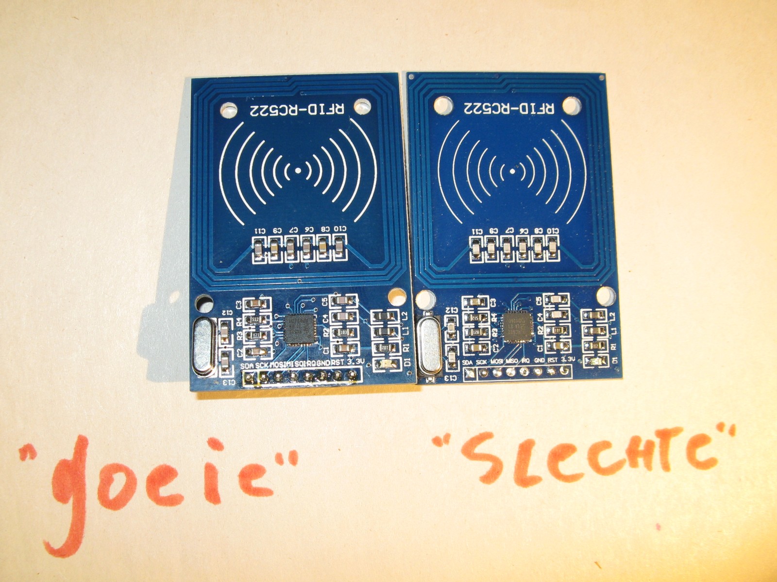
Those “Bad” card readers only read the blanc card and key-fob supplied with them (See “generic ad” picture). Other cards, such as the OV-chipkaart, coffee machine / copier machine cards, single-use OV-chipkaart, bank cards, and other access cards are not being read. The RC522 card reader should be able to read those cards because the MFRC522 IC that the reader is based on “supports all variants of the MIFARE Mini, MIFARE 1K, MIFARE 4K, MIFARE Ultralight, MIFARE DESFire EV1 and MIFARE Plus RF identification protocols.” (Quoting from it’s data sheet). The “Good” card readers do indeed read all those 13.56 Mhz RFID cards.
I’m taking steps!
Step one was to identify the various variants of this module and categorize them based on their (dis)ability to read various cards.
It appears there are a few subtle visual differences between the “Good” and “Bad” modules. (Apart from the difference that “Good” readers read all cards and “Bad” readers only read the cards that come supplied with them). So I took pictures of those variants of cardreaders, they can be found below.
Next step was to find out why the “Bad” modules aren’t reading OV-chipkaarten etc. and if this might be fixable so they do read all kinds of MIFARE / ISO/IEC14443-4 cards. (Spoiler alert: Yes, it can be repaired. Replace C8,9,10 and 11, see further down)
There has to be a difference:
And these are the differences between “Good” and “Bad” card readers:
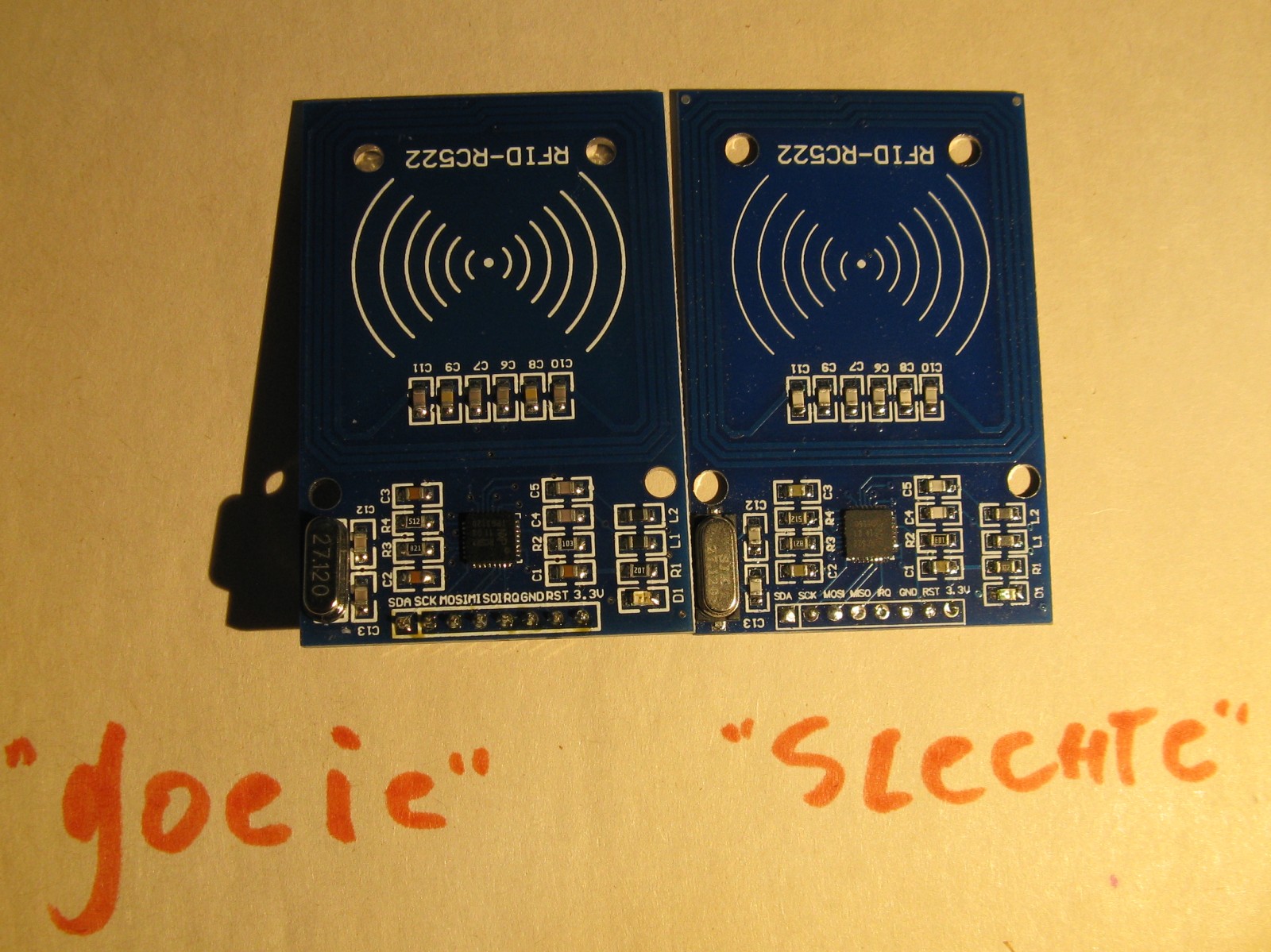
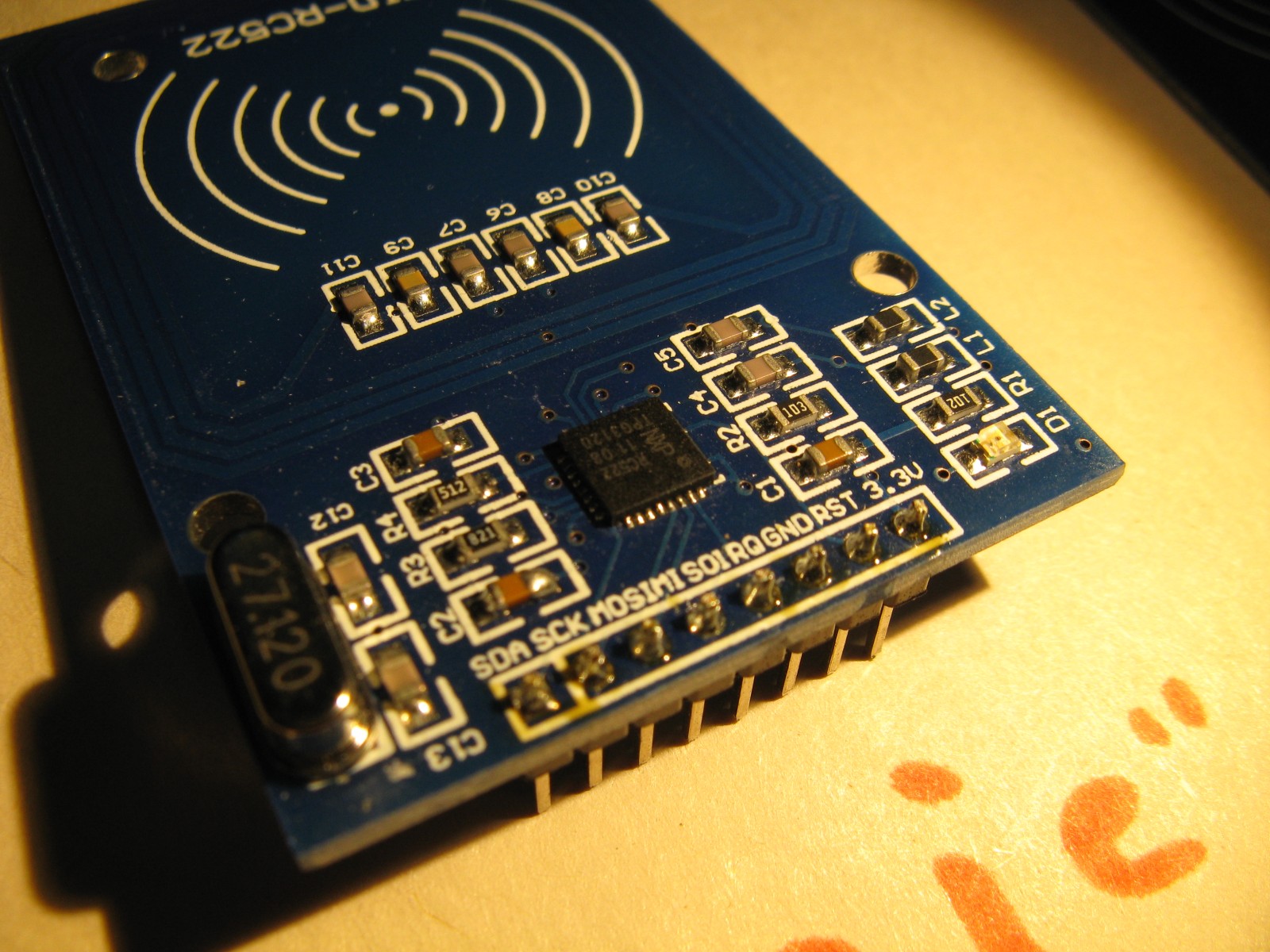
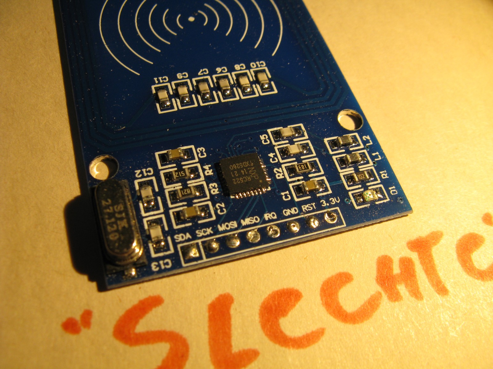
Notice the color of C4,5,6,7,8,9,10 & 11 is different, and note the location of the silkscreen text of C2,R3,R4 and C3.
The “Bad” readers use another type of capacitor, the color difference is not the cause of the problem, but it might be a good visual cue. (The difference is in the antenna coil as the capacitance of the capacitors measures the same, a “white” C6 is equal in capacitance to a “brown” C6.) The difference in the antenna coil cannot (easily) be seen.
The silkscreen text location is another visual cue. It again is not the cause of the problem.
The small dots (in top left and right corner) on the “Bad” reader are fiducials, a visual aid for the pick-and-place machine, and do not influence the functioning of the board. They can also be a visual cue to distinguish between the varieties of RC522 readers. (As they are all called RC-522)
On this second picture (above) the difference in antenna coil can be seen, the traces are a little narrower and further apart on the “Bad” reader. This difference is very hard to spot “in real life”. (But probably the reason the inductor has different characteristics)
It turned out there is another variant of the “Bad” card reader. It, too, does not read other cards than the ones that come with it:
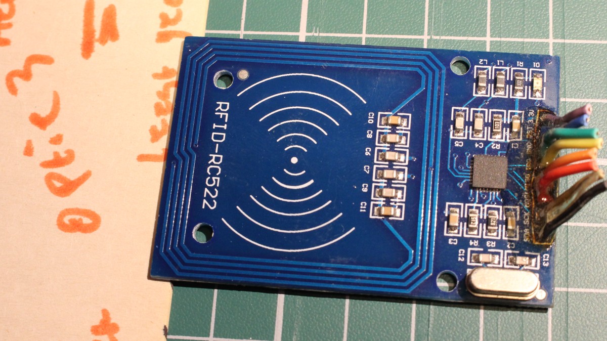
Visual cues that stand out on this circuit board are the non-plated mounting holes, the fiducials next to the crystal (bottom right) and in the top-left corner of the antenna coil, and the silkscreen has a slightly different and more glossy color. The silkscreen location of C2,3 and R4 are the same as with the “Good” readers, don’t let that fool you.
Here, again, these visual cues are not the cause of the problem, just a way to distinguish this kind of RC-522 from all other kinds of RC-522 all named RC-522.
Based on those pictures one could try to buy “Good” card readers that do read all cards. However: you don’t always get exactly what’s in the picture and those subtle differences can be difficult to base a claim on, so YMMV and please let me know if you tried this. Probably there are more variants on the market than I photographed.
How To Fix
This is of course the most important bit: How can those “Bad” card readers be repaired so they do read all the cards they should be able to read?
I swapped the IC between a “Good” reader and a “Bad” reader. The “Good” reader could still read all cards, so the chips themselves are not the cause in this case.
The “Bad” readers from the first pictures where found to have a too low resonant frequency of the antenna*. (I did not measure this on the “Bad” reader variant discovered later so I don’t know if they have the same problem, so I don’t know if this howto works for them)
The antenna is an L-C circuit so the resonant frequency can be corrected by modifying the capacitance or the inductance. Since the inductance is fixed (the inductor is etched on the PCB), the capacitors remain. There is about 210pF (C8+C10 == C9+C11), this should be lower to increase resonance frequency. About 185pF works fine.
Simple howto for everyone with a good soldering iron. “Just 2 simple steps”:
- Remove C8,C9,C10 en C11. This can be done with hot air and tweezers, or for those without the luxury of a hot air rework station: by applying so much solder both contacts of the capacitor can be heated on the same time, so it can be slid away.
- Place new capacitors. C8 and C9 each 150pF. C10 and C11 each 33pF. (0805 NP0, 50V). (180pF for C8 en C9, while leaving C10 and 11 open might also work, but I didn’t have 180pF on hand. Stacking 47pF multilayer also works but this was meant to be a simple how to).
(All right, 3 steps. Step 0 is buying 0805 150pF and 33pF capacitors, but since there is no web shop offering me sponsoring, there is no direct link to any shop here.)
Notes
* measurement result Made with a “Bad” reader (Of the first kind) and a miniVNA Tiny (I was very happy to get the offer to borrow a MiniVNA from a friend. The VNA has been returned to it’s owner now.)
More
In the Dutch equivalent of this blogpost and also in Dutch on the MakerSpace wiki.
“Part 1” in the title implies a part 2. It’s still unwritten though…
Questions, thoughts, remarks? Leave a comment!
Leave a Reply to tERBO Cancel reply