Category: ontwerpvouwtjes gladstrijken
-
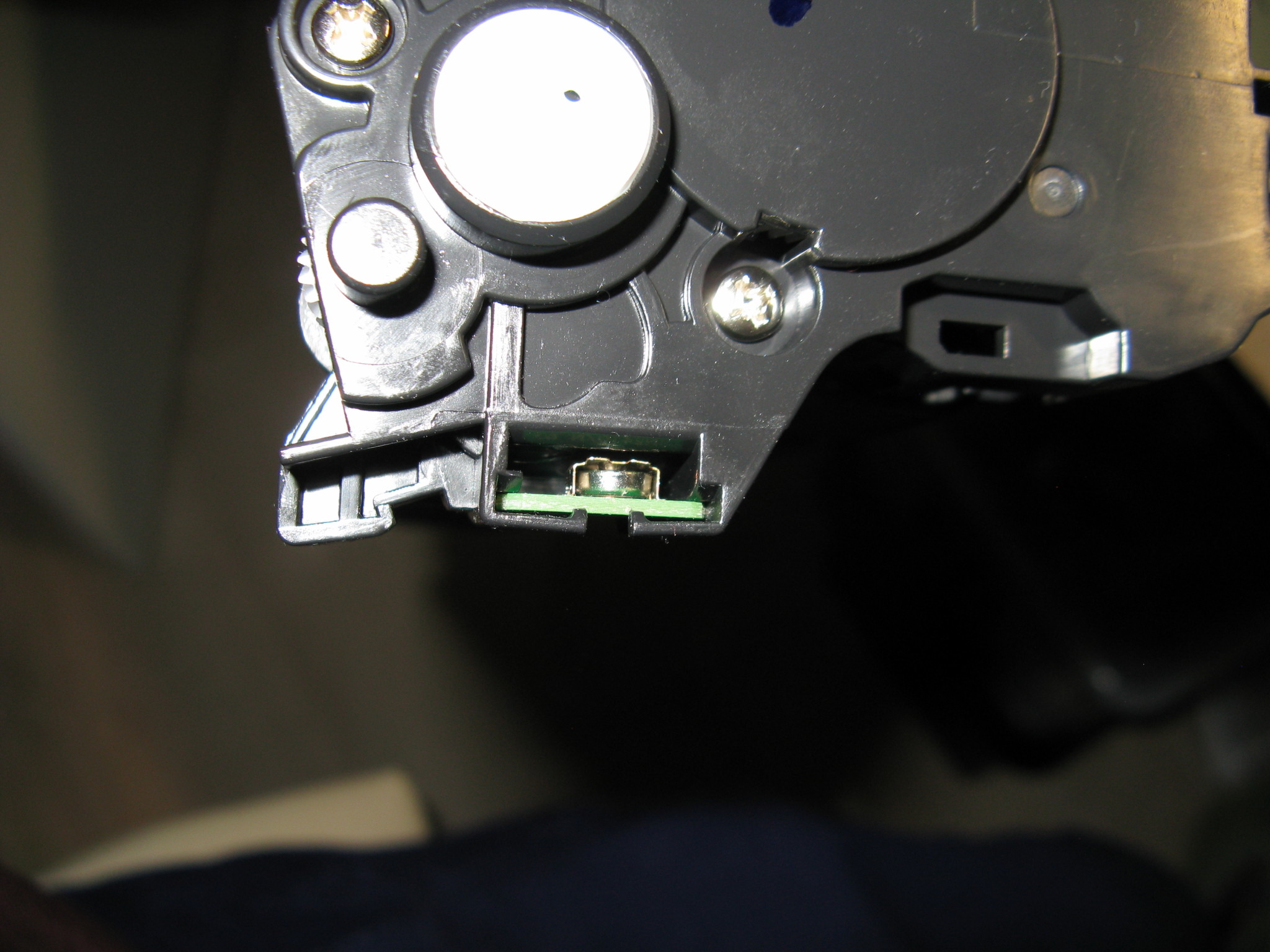
Knoopcel in Tonercartridge?
Mijn vader heeft een printer, en als daar een probleem mee is wordt ik er uiteraard bijgeroepen. Dit keer was de knoopcel in de toner leeg. Da’s weer eens wat anders dan de gebruikelijke printerproblemen. De printer zegt “kan niet detecteren” en weigert te printen. Het batterijtje is een L521F (LR521 / SR63). Het levert…
-
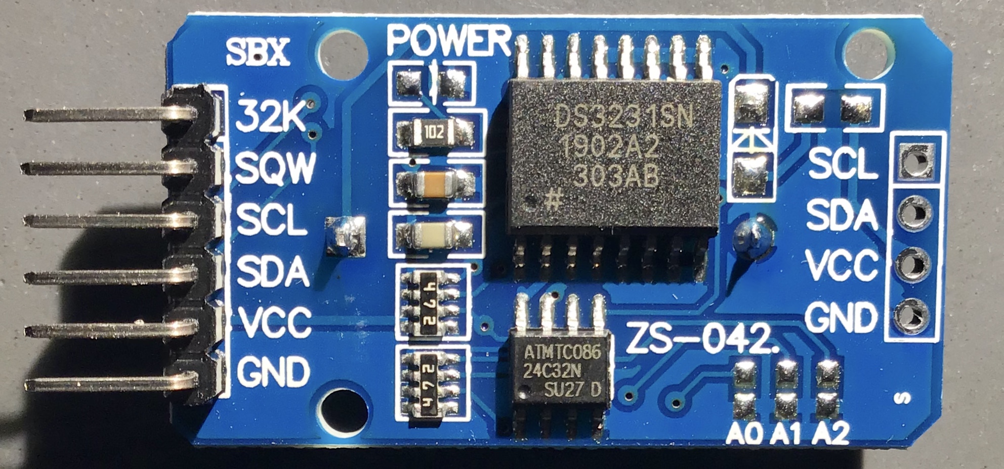
Real Time Clock modification
I bought one of those DS3231 Real Time Clock modules: I noticed it has a diode and resistor to charge the battery on the back. But I plan on using a non-rechargable CR2032 cell. So these had to be removed: I also removed the power LED, since I plan on using it in an alarm…
-
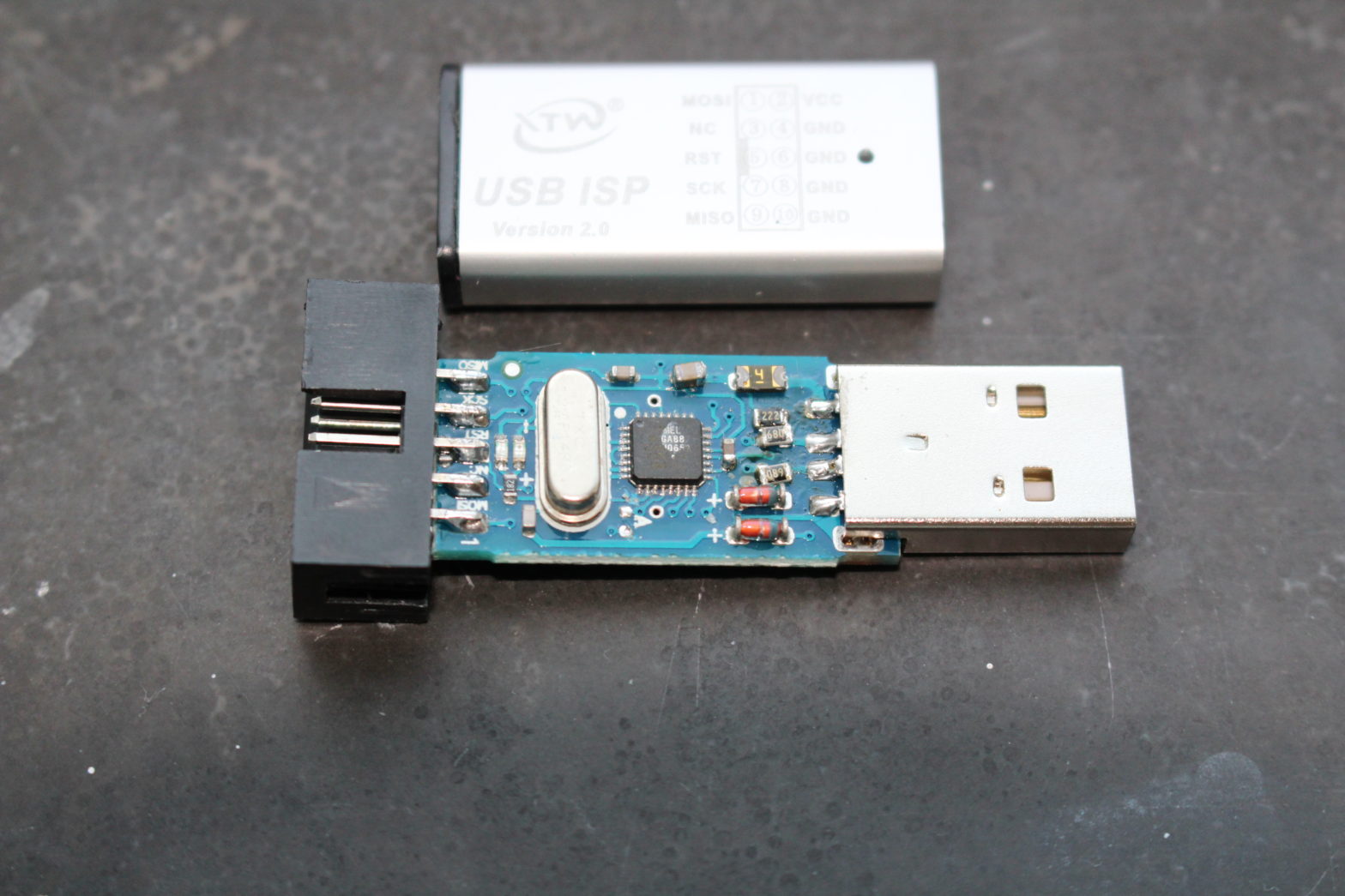
USBisp V2.0 to USBasp conversion to use TPI (or: USBisp did not connect to usb anymore after fw update – fixed!)
Recently I bought an USBasp, or at least that’s what I thought. I bought a clone that was advertised as “USB ISP USBasp USBisp Programmer for 51 ATMEL AVR download support Win 7 64 (RANDOM COLOR)”, marked on the case as “USB ISP version 2.0” and “MX-USBISP-V5.00” on the PCB. I intend to use this…
-
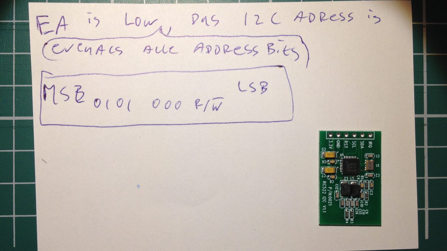
RFID Deel 2 (Of: enkele losse eindjes)
In aanvulling op Opgelost: RC522 RFID lezer leest (sommige) kaarten niet. (Deel 1): Eigenlijk heb ik een groot deel van wat ik van plan was in deel 2 te schrijven, toch al in deel 1 verwerkt. Er zijn echter een paar “losse eindjes”. Van de blauwe kaartlezers uit deel 1 bestaan vele varianten (ook in…
-
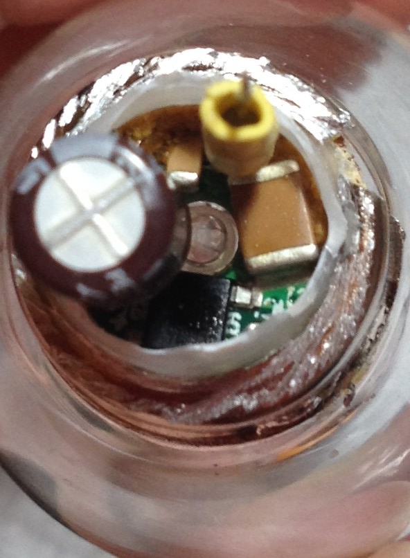
Sencys Ledlamp teardown
Dit is een ietwat stream-of-consiousness (Maar dan leesbaarder (hoop ik)) blogpost over een… Ledlamp! Enjoy! Ik ergerde me er aan dat mijn sencys™ filament kaarslamp knipperde. Vanaf dat ‘ie nieuw was zat er een 100Hz flikkering in het licht, wat te zien is als “stroboscopisch effect” bij alles wat beweegt in het licht van zo’n…
-
![[fixed] TM1637 LED display “not working”.](https://www.eluke.nl/wp-content/uploads/2018/03/lowres_tm1637_done.jpg)
[fixed] TM1637 LED display “not working”.
Last week I got 2 of these displays from a friend who couldn’t get them to display anything. (He knows I like those challenges.) Below picture proves it now works. What was the case: The data sheet says (e.g. in the schematic at page 8) a 100pF capacitor should be placed on CLK and DIO…
-
[gefikst] TM1637 LED display “doet niks”.
Afgelopen week kreeg ik 2 van deze displays van een vriend die ze niet aan de praat kreeg en weet dat ik van dergelijke uitdagingen houd. Op bovenstaande foto het bewijs dat het inmiddels gelukt is het displaytje wél aan de praat te krijgen. Wat was het geval: In de datasheet staat (o.a. in het…
-
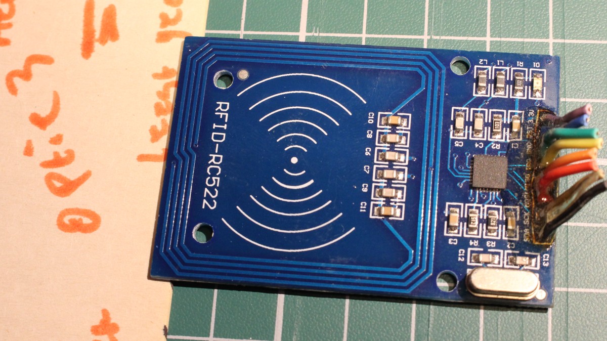
Fixed: RC522 RFID reader not reading (some) cards (Part 1)
Some of the RC-522 RFID card reader modules that can be bought on ebay / aliexpress have a problem: they do not read all (types of) cards they should be able to read. In this blog post I want to explain how to recognize these faulty readers and how to fix them. (There is a…
-
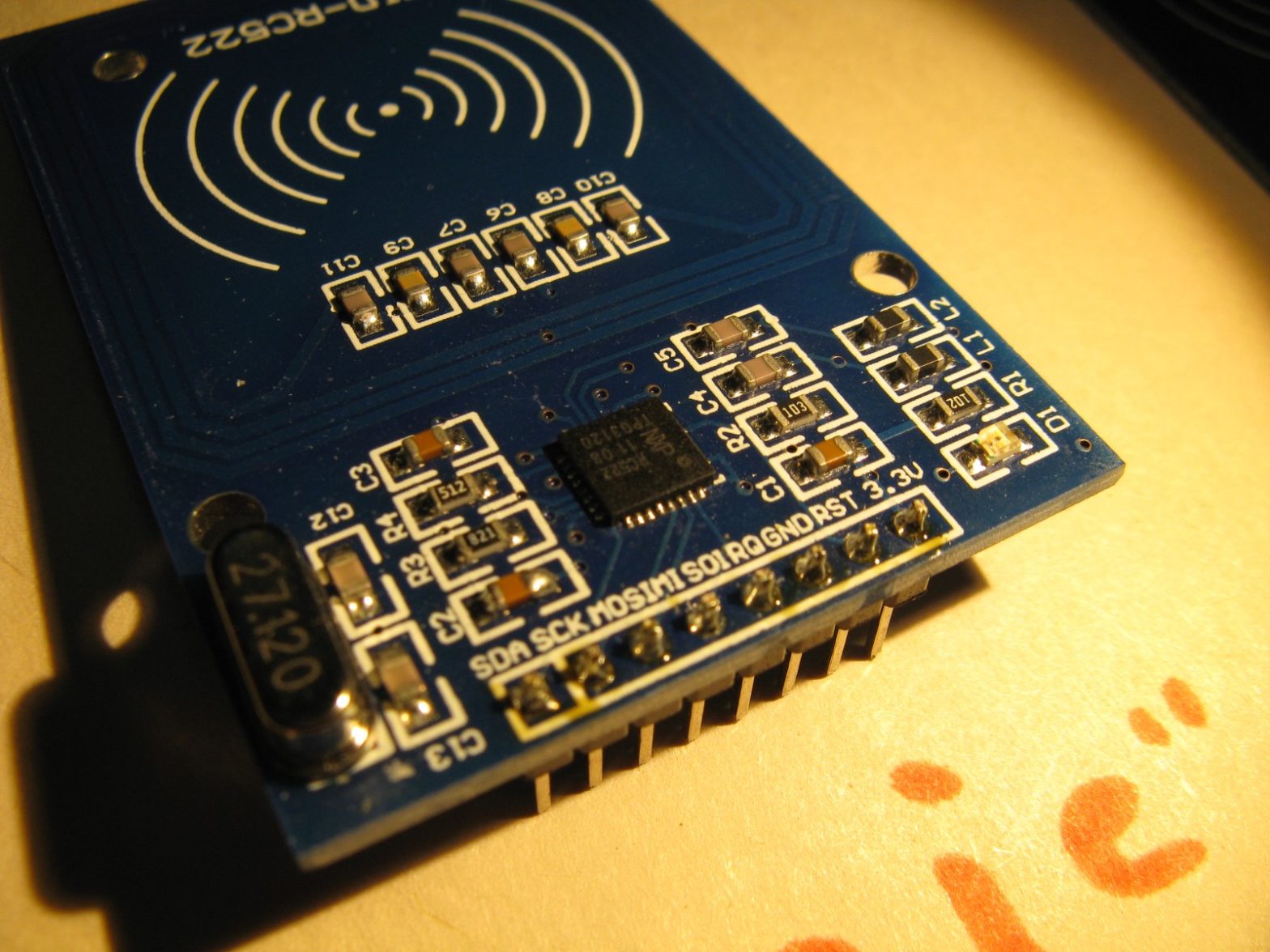
Opgelost: RC522 RFID lezer leest (sommige) kaarten niet. (Deel 1)
Ik heb recent een probleem ontdekt met de RC522 rfid kaartlezer modules die men op ebay / aliexpres en dergelijk kan kopen: ze lezen sommige kaarten niet. In deze blogpost wil ik uitleggen wat het probleem is, en hoe het opgelost kan worden, in de hoop dat mensen die hetzelfde probleem tegenkomen daar wat aan…