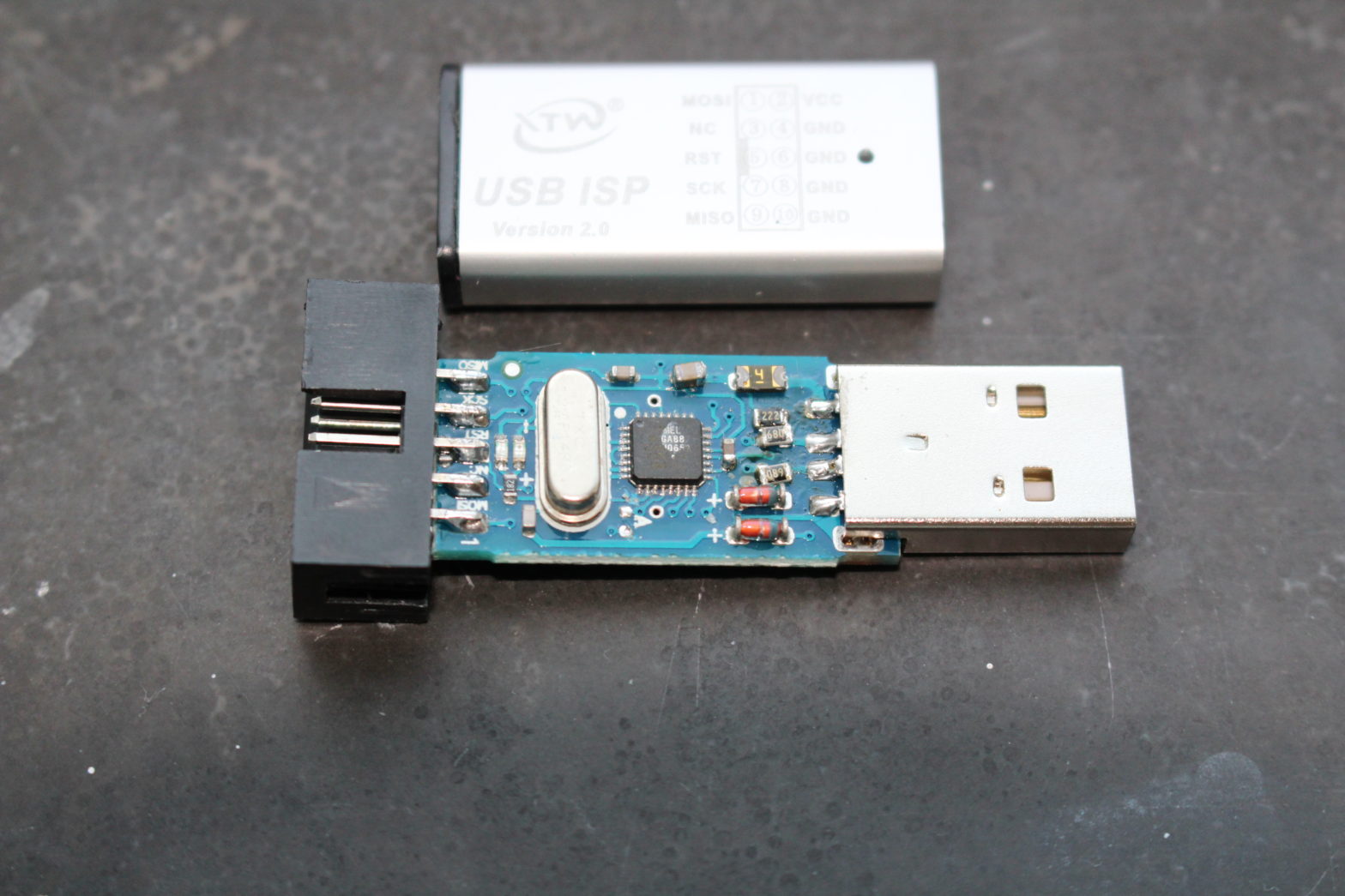
Recently I bought an USBasp, or at least that’s what I thought. I bought a clone that was advertised as “USB ISP USBasp USBisp Programmer for 51 ATMEL AVR download support Win 7 64 (RANDOM COLOR)”, marked on the case as “USB ISP version 2.0” and “MX-USBISP-V5.00” on the PCB.
I intend to use this as a TPI programmer for attiny10, so I need the USBasp firmware that supports this. But it turned out not to be compatible… Unless the hardware is modified 🙂 . (So that’t what I did)
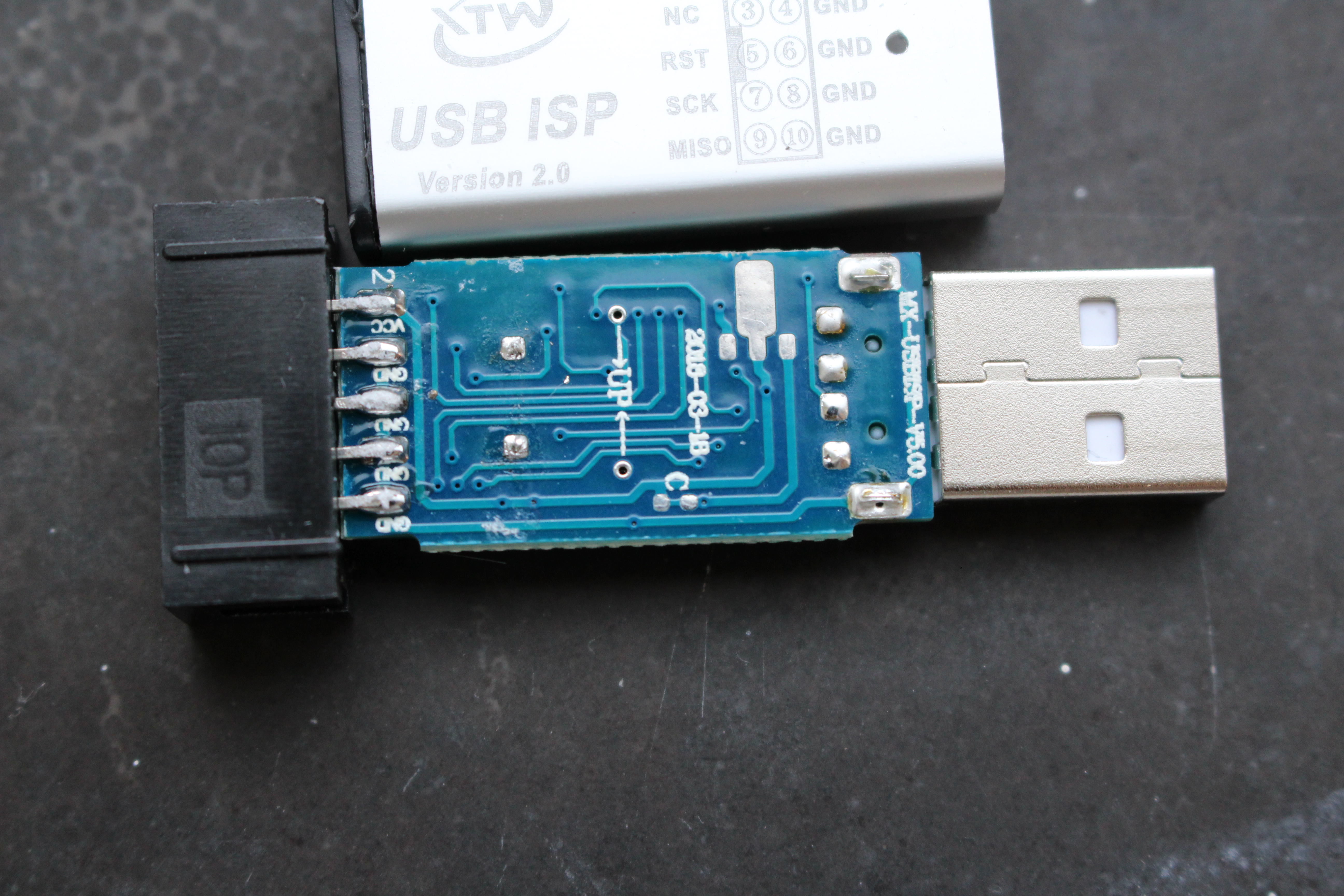
Upgrading the firmware is easy. Connect the 10pin connector to another programmers 10 pin Atmel ISP connector, put a jumper wire on the USBasp “update jumper” (Labelled “UP” in above picture), power the “usbasp-clone”, and load the new firmware using the other programmer. Plenty tutorials for that at various places on the web.
However… Before I updated the firmware, the USBasp was seen by my computer, as an “Atmel Incorporated”. After the update, it did not connect any more. It did not show with “lsusb”, and nothing in “dmesg” either. So, after the update, it does not work any more. I broke it. Let’s see if I can fix it too.
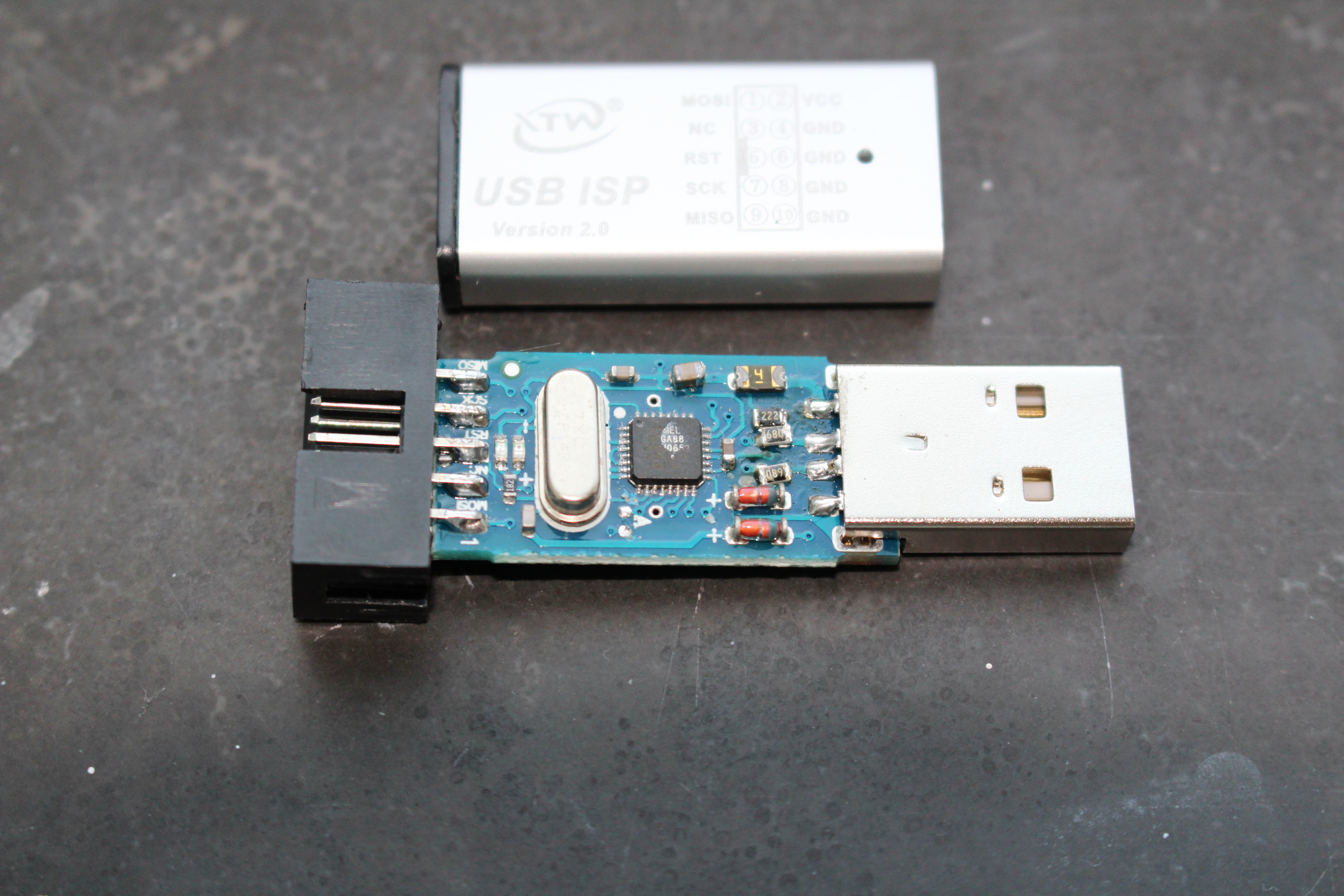
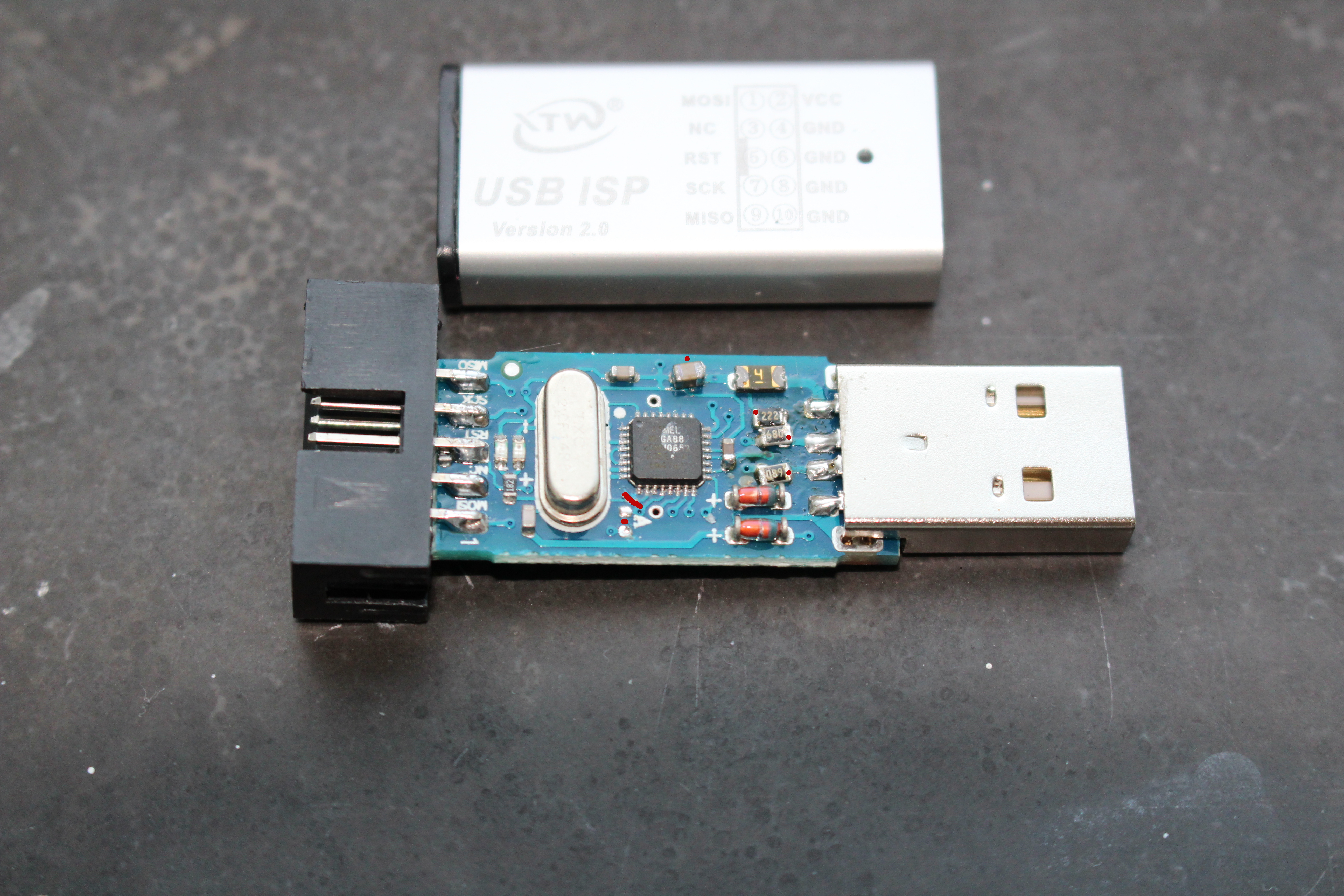
Turns out, the USBisp v2 I bought has a slightly different schematic. Among other differences, there is a 0R resistor on the board that connects one of the USB lines to another MCU pin (PD3). PD3 is unconnected in the original schematic. After removing this resistor, it worked again and connected to my PC as a “Van Ooijen Technische Informatica shared ID for use with libusb”, and it is usable with AVRdude as an USBasp (I tested reading an attiny10’s flash, and it worked).
Before that, I tried other modifications that might be needed also, but that by themselves had no effect. The other differences where that my board had a 1k8 pull-up on the USB D- line (R3 in original schematic), and R1/R2 where 100 Ohms instead of 68. So I replaced those resistors with the original values, just in case, but I think it would have worked with 1k8 / 100R.
Also I cut the trace from PD6 to one of the LED pins, as that connection is also not in the original schematic. And while I was at it, I added a decoupling cap on a vacant spot on the PCB and soldered the mechanical pins on the USB connector.
After all these modifications, it looks like this:
So now, I have a TPI programmer for my Attiny10’s. And if you bought the same or a similar enough USBisp or USBasp and ran into the same issue putting USBasp firmware on it, now you know how to fix it 🙂 (See first picture for PCB & case markings).
Leave a Reply