Specially for those desiring to build their own neon-indicator watch, or for those who just want to know how it’s made (Bunch a’ enginèèrds! 😉 ). In this blogpost I’ll share the design files1. (Ook in het Nederlands beschikbaar)
For those that rather watch the outside of the watch: here is a link to the blogpost about that.
Aesthetic design considerations:
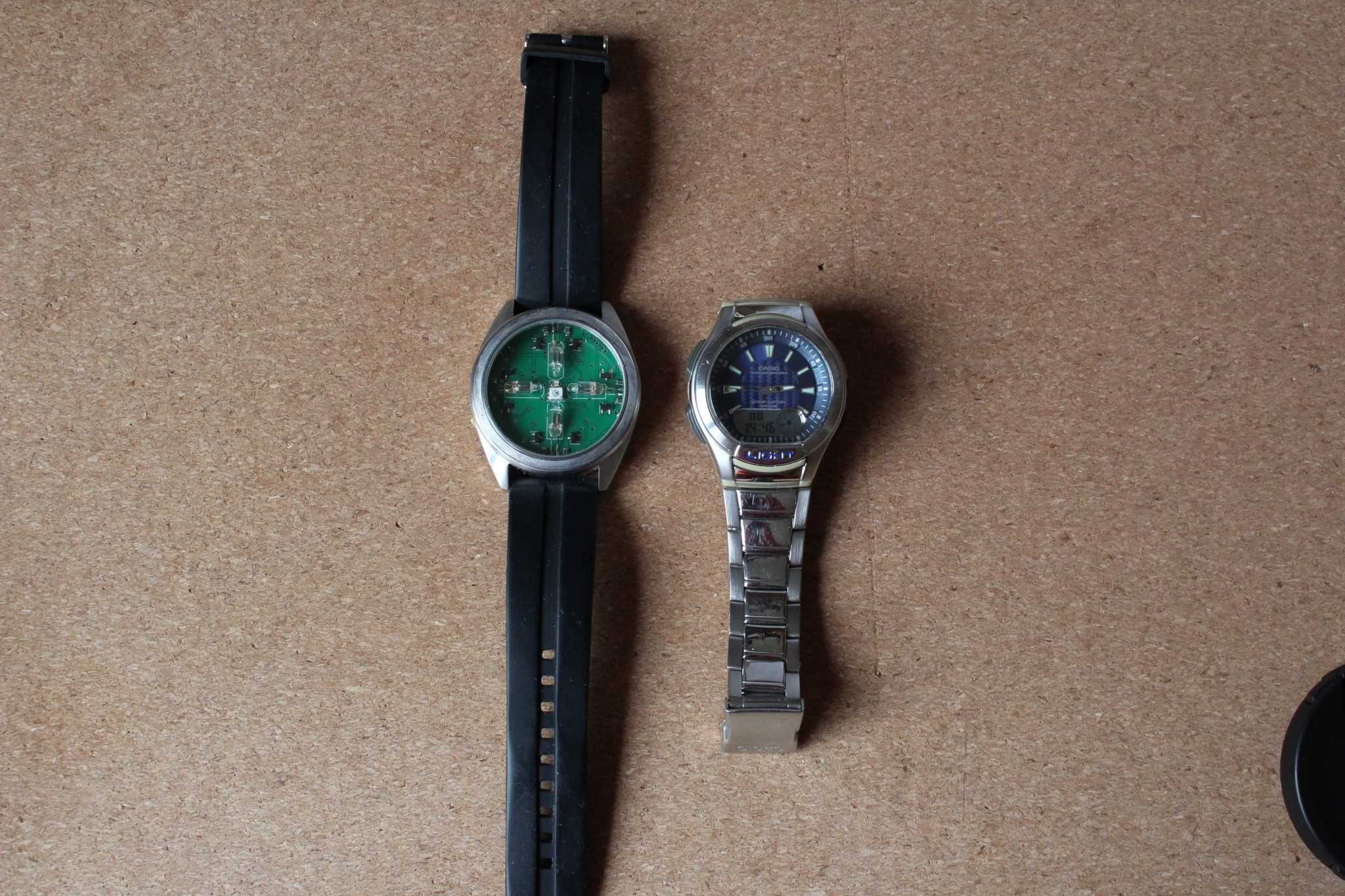
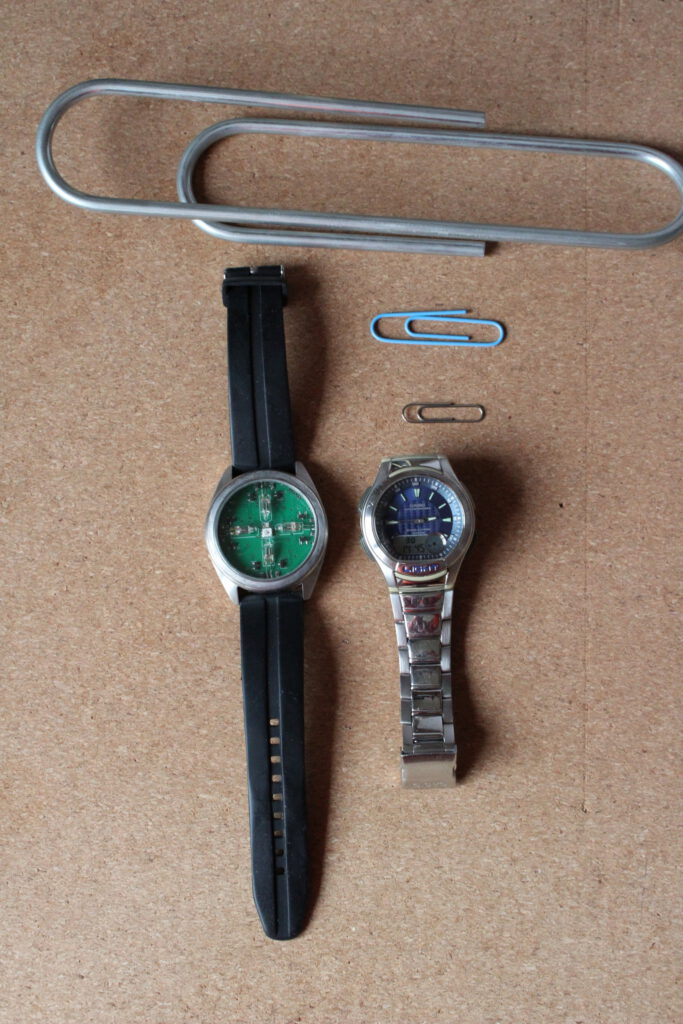
I re-used an existing watch case for the neon watch, because it seemed to me that would look nicer then a 3d-printed home-made watch case. Someone who can work magic with lathes and milling machines may make a different decision.
The 4 neon lights are symmetrically distributed over the dial. I previously considered a binary neon watch with 3 lights, but I didn’t like it. See below 3D- renders:
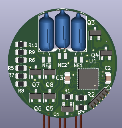
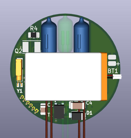
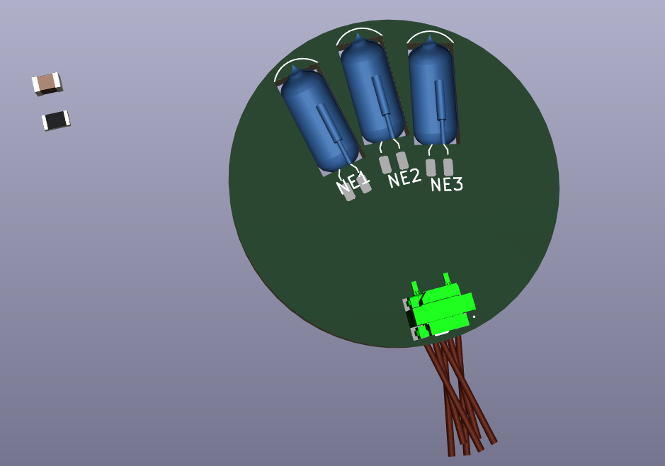
Having a cut-out in the board to place the neon indicator lamps in would have been a possibility to gain more room in the ‘thickness’ of the watch, but this would be at the expense of room for tracks and for parts on the bottom layer. That would make routing the board difficult (and/or ugly) so I choose not to recess the neon lamps into the board but instead keep them on te surface.
Hardware / software design considerations:
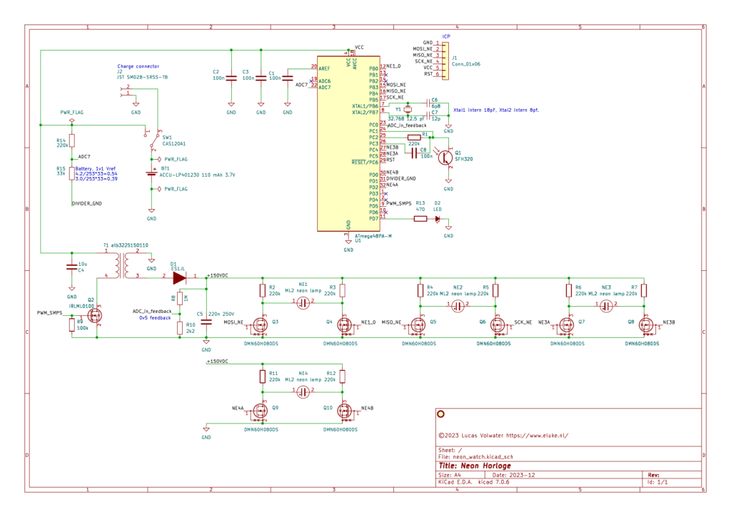
Instead of a voltage divider to measure battery voltage, I could have used the method2 outlined in Microchip appnote 2447. But since it is easy-er to not place a couple resistors on a board that has space for them, then it is to add a few to a board that has none, it is simply there.
The phototransistor is connected to 2 ADC inputs, once DC coupled and once AC coupled (trough C8). This would make it possible to do things like the distance sensor I posted a while ago, combined with the LED next to the photo-transistor. However, in the current watch firmware I make no use of this. Also, I have not tested it with this hardware setup.
There are lots more considerations, feel free to ask in a comment if there is anything you would like to know.
How does setting the watch work?
Here is the blogpost detailing the transmitter side of the optical data transmission for setting the watch.
Reception is done by sampling the light sensor at a fixed rate. By counting the number of samples that where ‘Dark’ the moment it turns ‘Light’ it is determined what is a ‘ 1’ or a ‘0’:
A 1 is 40 ms “dark” followed by 80 ms “light”.
A 0 is 80 ms “dark” followed by 40 ms “light”.
A bit normally takes 120 ms in total. The watch restarts at the zeroth bit of reception when the period of “Light” takes over 156 ms. (that’s 10 samples 😉 ).
How to build and use
A few parts are difficult to solder, like the ATMega48A in QFN (no pins) and the tiny 0402 capacitors near the watch crystal. With (low temperature) solder paste, hot air, and a good pair of tweezers it is possible but please consider this before having a circuit board made3. Also consider there is no charger4 on the board.
Populating the board can be done based on the schematic or the parts list. After all parts are soldered and a power supply is connected, the firmware can be loaded into the ATMega48A with a programmer of your choosing. The pin-out for the connector is in the schematic. A 1 mm pitch header can be used as a temporary connection.
When the watch is switched on it won’t function until it is set. For that use the python software (or build a ‘lichtwekker’ 😀 ).
This zip archive contains all design files: schematic (pdf&kicad), pcb design (kicad&gerber), firmware for the Atmega48A (.hex and source), and the python software.
I like hearing form you if you have build (or plan to build) a neon watch like this. Please leave a comment or send me an email.
Footnotes:
- For non-commercial use. See also attached ‘License’. ↩︎
- That application note explains a method to calculate the supply voltage by using the supply as ADC reference and measuring a known (internal reference) voltage. That way there is no need for a voltage divider connected to an ADC input pin, hence no current through the divider and the pin is free for another purpose ↩︎
- Or perhaps ask me if I still have boards, but considering international shipping maybe don’t ↩︎
- A ‘single cell charger’ board as is offered by the usual traders might be an option, when it is set to a suitable charge rate (maximum 110mA for the 110mAh LP401230 battery) ↩︎
Leave a Reply