Because there is no big news yet, some short updates.
– Claude Schwarz pointed me to the Yahoo user group “Lecroy Owners group”, they have design files for a HHZ406 replacement. (Made by Dieter Frieauff). So maybe the ext. trigger input can be repaired as well.
– A service manual for this ‘scope (And others) can be found there as well, or alternatively here: http://www.ko4bb.com/manuals/index.php?dir=LeCroy (Or on elektrotanya.com – but that site is full of ads)
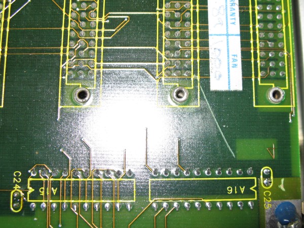
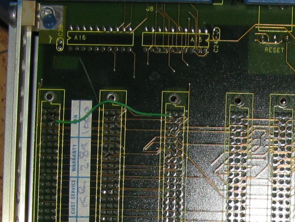
– NoTMS was caused by a missing “Vct”, I accidentally scratched trough this trace while placing the bottom cover. Took quite some time to find, then just a little wire to fix.
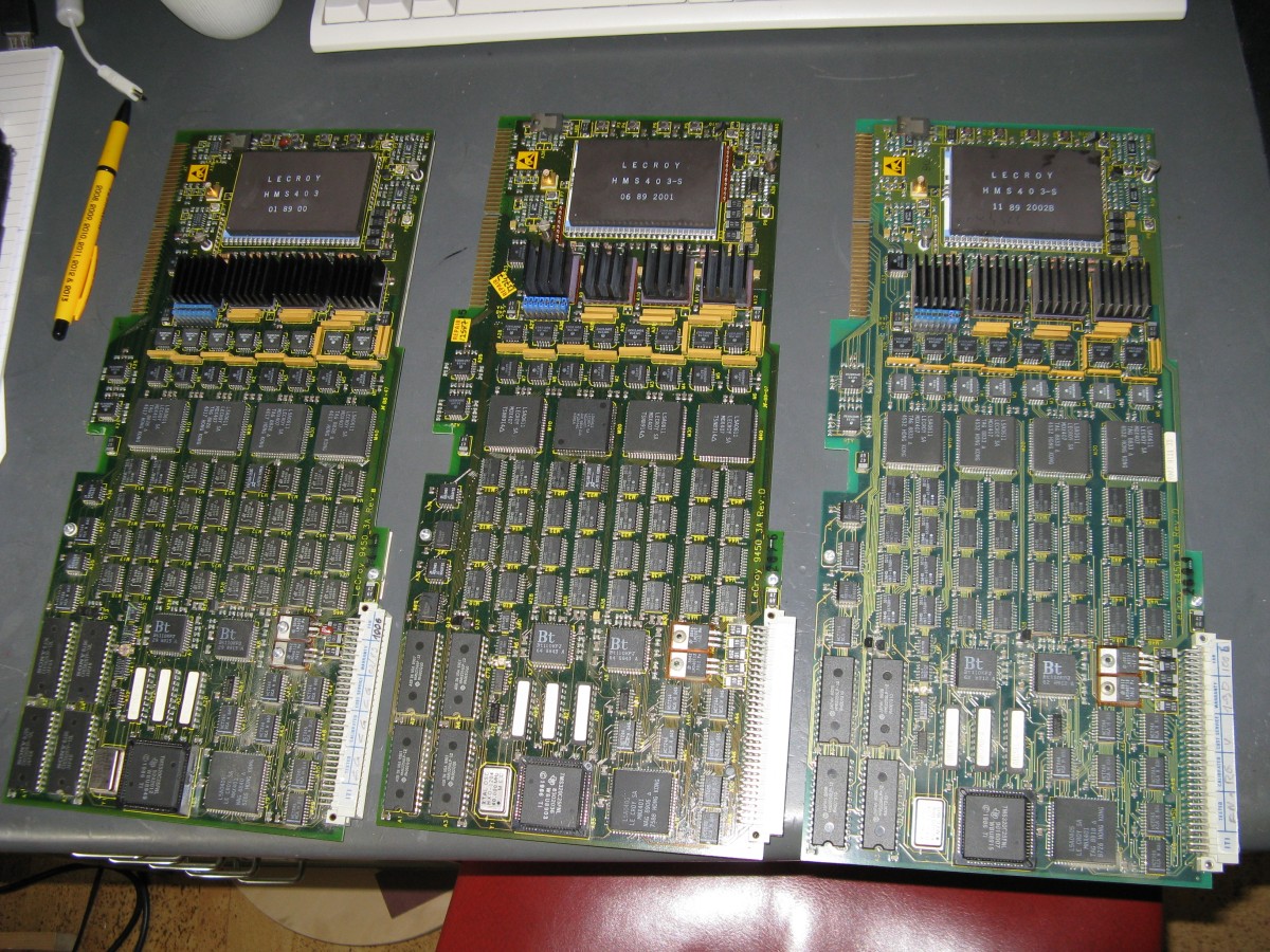
– Thanks to Claude Schwarz (Again), I now have a third ADC card. So I now have spareparts, and if I get one of the 2 broken cards working again, a working 2ch 350Mhz / 400Ms/s (10Gs/s) DSO. (Or rather: the Leidse Makerspace then has a 2ch 350Mhz DSO). The 3 ADC cards will hereafter be named “9450_3A Claude”, “9450_3A LMS-Broken” and “9450_3A LMS-Working”. (order shown in the picture, ltr: broken, Claude, working )
– I measured the power supplies on “9450_3A LMS-broken”. All are present. (-5V, -12V, 5V and +12V). Next up: reference voltages and tracing the signal path.
– Some more pictures:
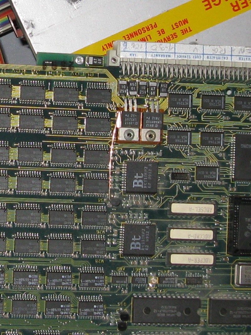 On some of the ADC boards, a 5V regulator is placed where others have just a cap.
This is another original patch (-5V regulator), both on “9450_3A LMS broken”. This board has no LeCroy repair stickers (shown below), but those patches were there when I got the ‘scope so I assume they are original.
Bot these 2 regulators and the -12V and 12V ones have the correct output voltages.

Lecroy Repair stickers on the timebase board. (This board is working fine) There are more of those stickers in the scope on other boards.
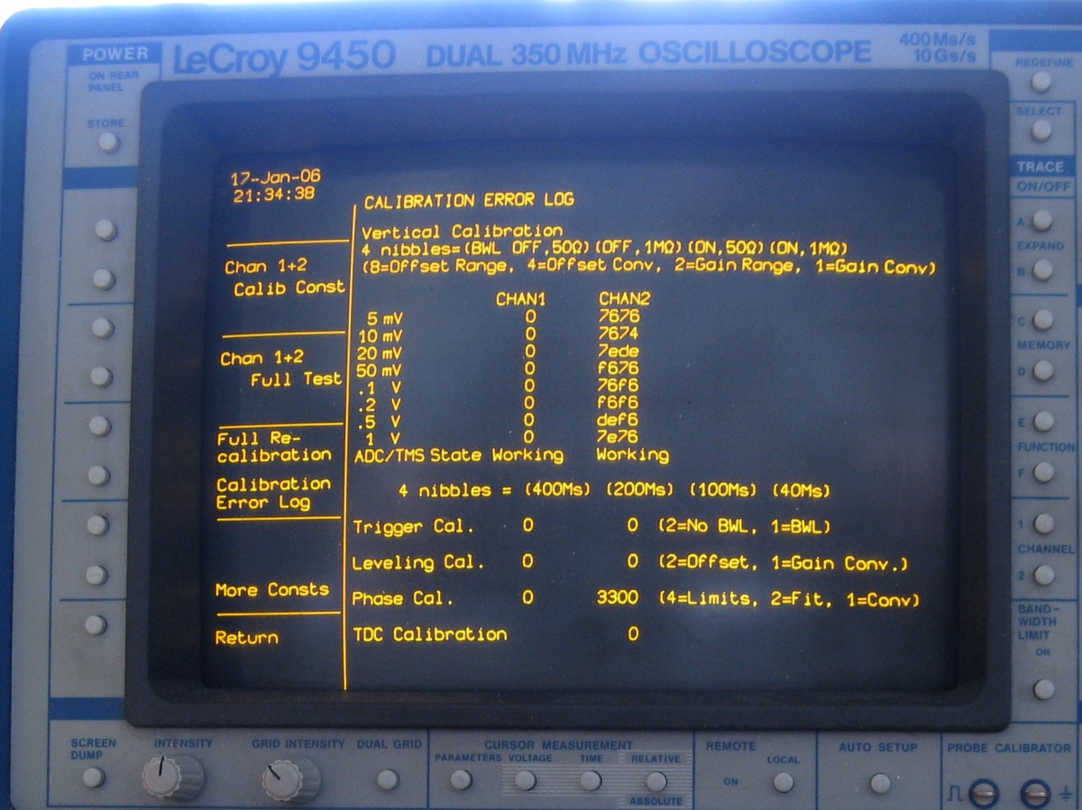
And the last one for today: The calibration error log. Chan2 has “9450_3A Claude” in this picture, but “9450_3A LMS broken” gives similar results. If I exchange the cards between the channels, ch1 gets the errors and ch2 is error-free. (The error-free channel has “9450_3A LMS working” in both cases).
‘ll keep you posted!
EDIT 2-7-2014:
“Next up: reference voltages and tracing the signal path.”
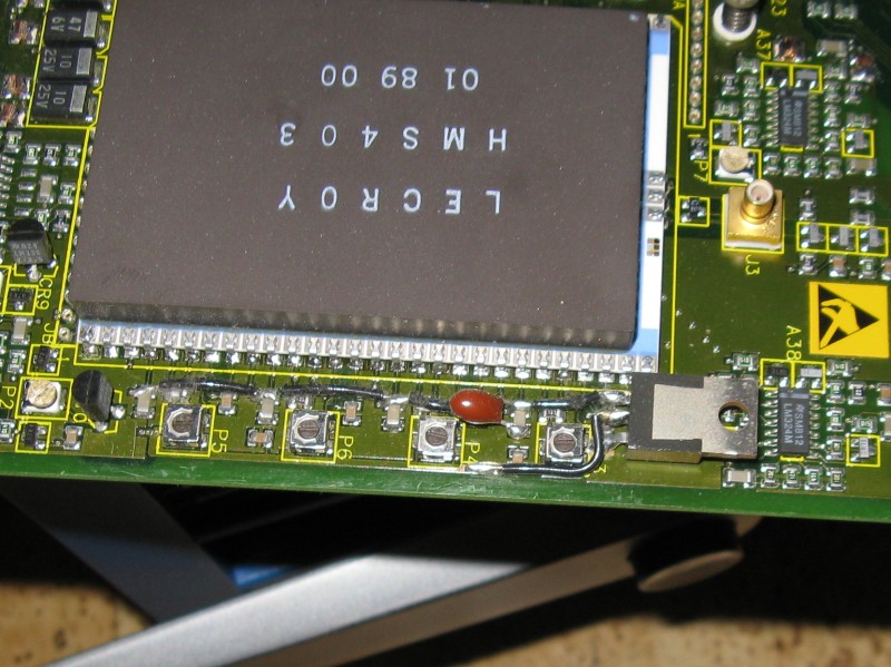
Measured on HMS403, seems to be OK. Also none of the ADC’s have stuck bits (did not log what bit connected to what line of the LA, but with no input all are 0, as long as there is no selftest / calibration running.)
Please note if you connect a logic analyser to these circuits they are negative logic (“1” is – 5V, “0” = 0V). As the 0V is connected to chassis ground, and your LA’s ground might also be (through the powersuply’s both connected to earth ground), use caution!
The scope does not do a memory test on boot up. I carefully removed one of the RAM IC’s to test this, and the scope does still show “ADC/TMS state working”.
So there might be something wrong with the memory. Fortunately this is normal TTL logic again.
EDIT 8-Aug-2014:
On slower sample rates this scope only uses 1 of its 4 ADC’s (per channel). On slower sample rates, the problem stays, 1 out of 4 points on the display (Maybe 1 out of 4 samples?) is out of line. So it’s not 1 of the 4 adc’s that’s broken (because it only uses one at that sample rate), but something in the memory or further in the data pad. The memory is also divided in 4 parts/banks, so it could just be… But for now I’m going to work on other projects for a while.
Please comment if you have any questions or suggestions!
Leave a Reply