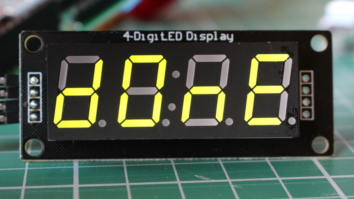
Last week I got 2 of these displays from a friend who couldn’t get them to display anything. (He knows I like those challenges.) Below picture proves it now works.
What was the case:
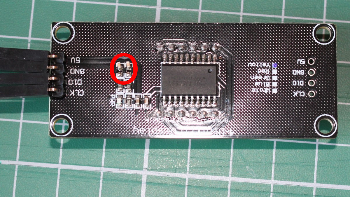
The data sheet says (e.g. in the schematic at page 8) a 100pF capacitor should be placed on CLK and DIO lines to GND.
verbatim quote from the data sheet: “100pF capacitor connected to the DIO, CLK communication port pull-up and pull-down can reduce interference to radio communications port.”
The capacitor is probably meant to reduce the signals rise time and thus reduce high frequency harmonics.
On the PCB, a 10nF capacitor was present, and that’s the cause of the display not functioning, just like overly long connections would cause this (when the wire length itself adds to much capacitance)
So, for those of you who bought one of these displays on Aliexpress, DX, or ebay, try removing those 2 capacitors (Or replacing them with 100 pF) if the display doesn’t work.
Leave a Reply to Ed Hayes Cancel reply