(This post is also available in Dutch)
For another project I’m tinkering with an old computer power supply. While I’m at it, why not see if I can build some crude current limiting. It does not need to regulate the current neatly, as long as it is short circuit proof.
A LED on the 12V output of a computer PSU would normally be blown to bits. Such a power supply can furnish ridiculously large amounts of current, while a LED only needs 20mA and as a diode won’t self-limit this. The PSU in the picture is an old one, the 12V line is orange instead of yellow. (The 3V3 is brown.) The 12V can deliver about 7A, 350 times more than the LED needs.
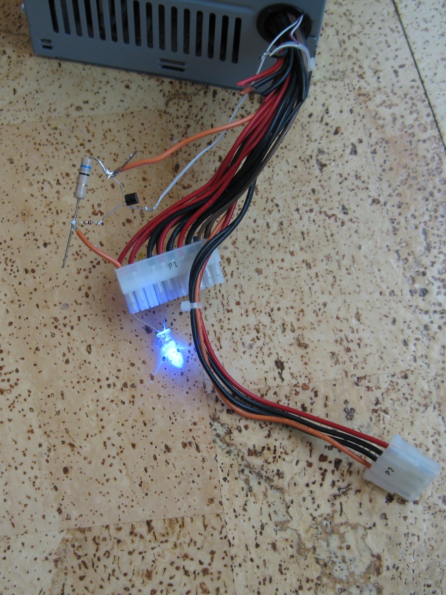
Yet, in this picture, the LED does not break, because I added some current limiting circuit. How does this work?
WARNING: Do not try this at home. Or anywhere else. Or at least don’t blame me if you do anything stupid and/or electrocute yourself. There are dangerous (potentially lethal) voltages inside a computer power supply. I won’t tell you to disconnect it from mains and discharge primary capacitors before you work on it, you should know already or else leave the cover on. Put that screwdriver down!
Voltage regulation in a atx computer PSU is done via optocouplers. The controller IC, UC3842 (or similar) is after all connected to mains power.
On the secondary side of the supply a TL431 is used to send current trough the LED of an optocoupler when the output voltage of the PSU goes too high. The TL431 is used as a comparator (it is a programmable zener / shunt regulator / voltage reference). The other side of the optocoupler is connected to the uc3842 so it lowers its duty cycle and therefore the output voltage.
At danyk.cz schematics of computer power supply’s can be found. Go there to see the voltage regulator circuit (And all the protection circuits I removed from my PSU)
A crude form of current limiting is actually quite easy to make.
By connecting a second optocoupler with its transistor side parallel to the transistor of the first, the output voltage will go down if the led in the second optocoupler gets activated. For the UC3842 this is the same situation as when the output voltage goes to high. So now all I need is a circuit that activates the second optocouplers LED when the output current rises to high, and I have a crude form of current limiting.
This circuit is not that hard. Every resistor has a voltage drop if there is current going trough it. Ohms law. So the output current can easily be measured by putting a resistor in series with it. A sense resistor. Then a transistor that starts conducting when the voltage over the sense resistor surpasses 0,7V. Have the transistor drive the LED from the opto, and that’s the circuit.
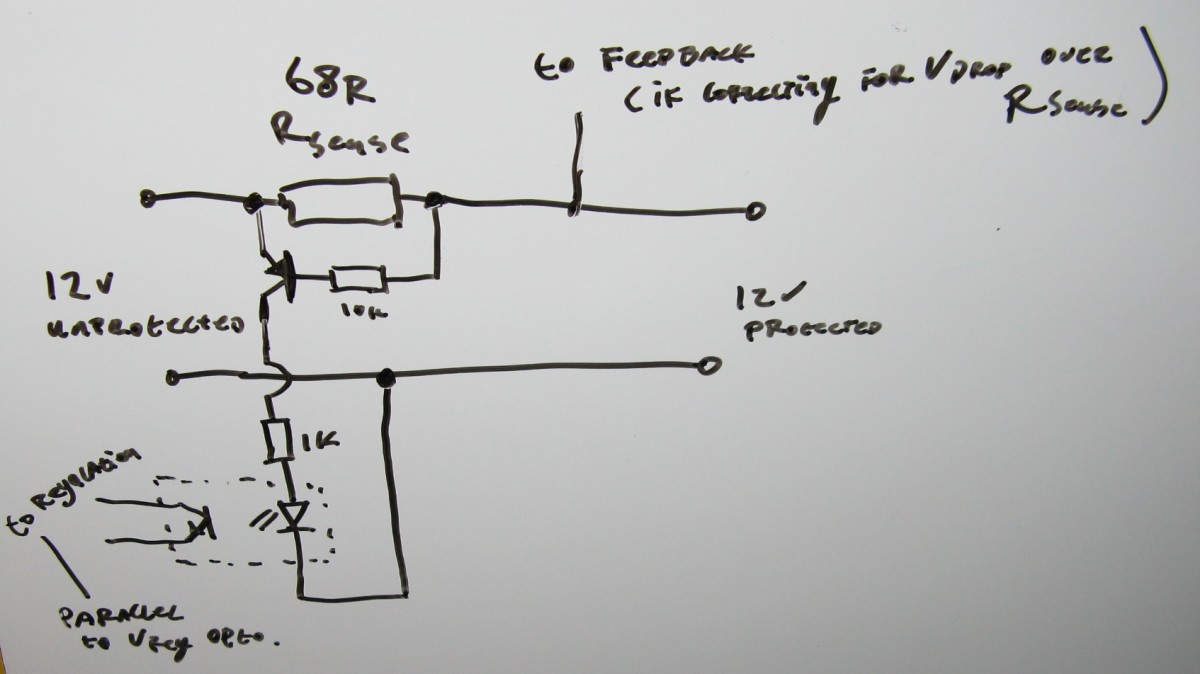
For this test the sense resistor is 68Ohms. This would be a current of 0,7/68R=10mA. Because the voltagedrop over the sense resistor can be annoying it’s possible to connect the voltage regulation feedback after the sense resistor so it will compensate. I have not done that for this test.
In practice I won’t limit the current to 10mA, but more likely to 10A, and the sense resistor would be much smaller (0,068R).
But for this test it’s fun to light a LED with a computer power supply.
The current limit oscillates, causing the LED to flash, see video below:
If instead of the LED I connect my ammeter, the value fluctuates between 10 and 20 mA, but probably the peak values are further apart and the meter can’t keep up with the change.
But for short circuit protection this works fine. A big disadvantage however is that the fan in the PSU is on the same 12V line and also gets tuned down / turned off when current limit kicks in.
Because all the “modified computer PSU” project i’ve so far seen on the web only mess with the output voltage and not with the current limit, I decided to post this in both Dutch and English in the hope that it will be useful to anyone, however this idea comes with NO WARRANTIES whatsoever. Please note the rectified line voltage inside those supplies is potentially lethal and capacitors might remain charged to this voltage even when the supply is disconnected from mains. Do not attempt this unless you know how to safely deal with this. If you do attempt this, you do so at your own risk.
Please let me know if you see a similar project somewhere that also deals with current limit on a modified computer powersupply.
Leave a Reply